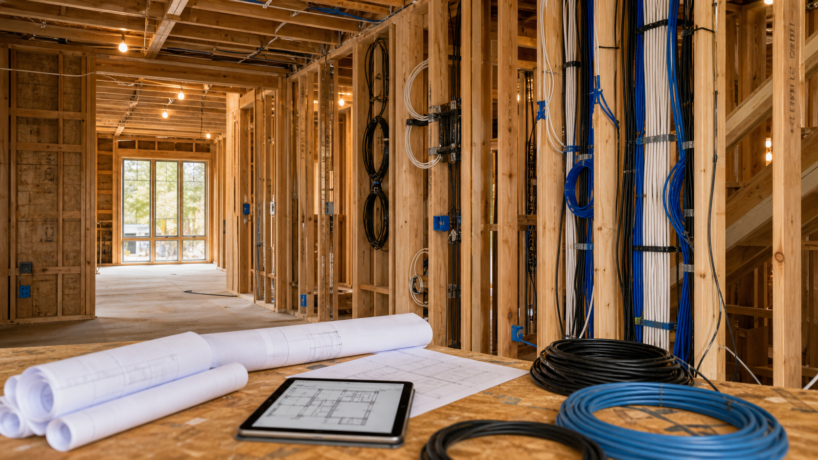
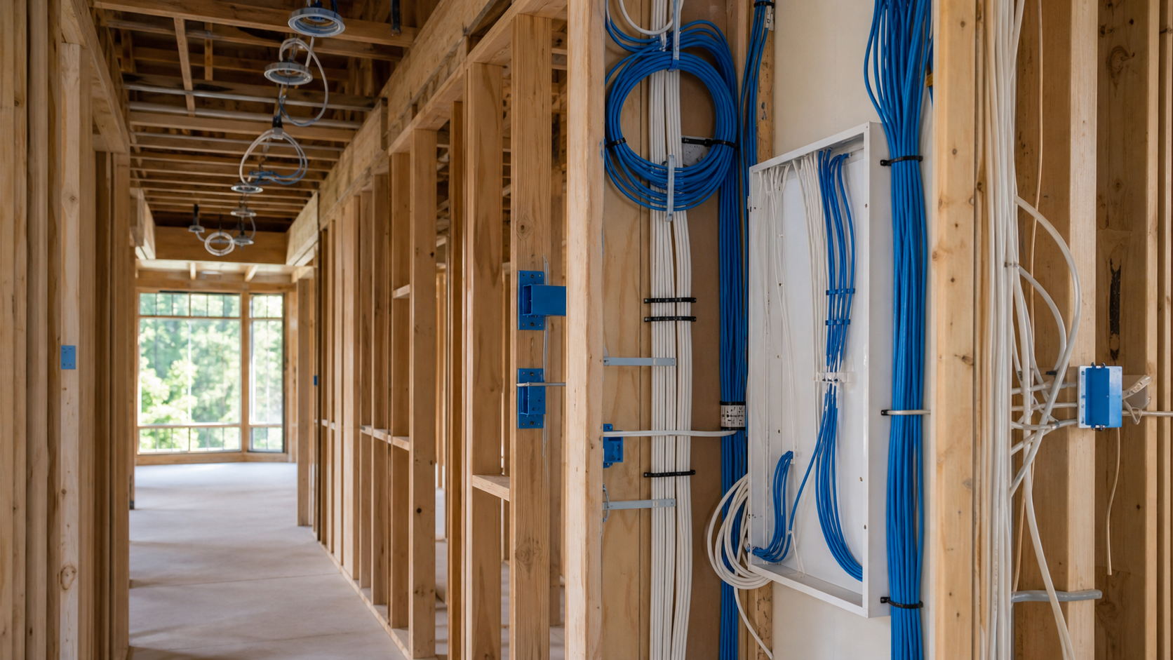
In Houston custom homes, low-voltage rough-in is the point where the hidden wiring plan has to match the finished design. Use this checklist during a framed-home walkthrough before insulation. The prewire does not need every final device model, but it does need marked locations, cable counts, pathways, power coordination, trade notes, and photos before drywall covers the work.
This checklist covers the field decisions ETG reviews with the homeowner, builder, designer, architect, electrician, HVAC team, and other trades before the walls close.
What Is Low-Voltage Rough-In?
Low-voltage rough-in is the pre-drywall stage when wiring and pathways are placed for connected home systems. That can include network data, wireless access points, TVs, speakers, cameras, doorbells, gates, shades, lighting control, keypads, sensors, and smart-home control.
The work looks simple when the walls are open. It gets harder after drywall, cabinetry, stone, millwork, and finished ceilings are in place. Confirm the checklist while boxes, brackets, cable paths, and ceiling bays are still visible.
Plans and Selections ETG Reviews
Before recommending a rough-in plan, ETG confirms that the project team agrees on the following points.
Start with the current plan set: floor plans, reflected ceiling plans, electrical drawings, cabinet elevations, furniture layouts, shade notes, security goals, and the builder's schedule.
Floor plans and elevations show the rooms, wall changes, built-ins, exterior living areas, and places where cabinetry or millwork may block a device. Reflected ceiling plans bring lights, beams, registers, sprinklers, speakers, cameras, and access points into one view.
Electrical drawings help coordinate power for TVs, shades, equipment, keypads, and exterior devices. Furniture layouts show how each room will actually be used. Shade and security selections add the details that are easy to miss: pockets, recessed tracks, side channels, door contacts, gate wiring, driveway coverage, patio coverage, and detached-building needs.
The review is not about forcing final equipment choices too early. It is about confirming the physical plan before the field changes become finish-work problems.
Who Should Be Involved in the Rough-In Review
This is not a one-trade decision. The builder understands sequencing and framing. The architect and designer understand how the finished spaces should look. The electrician coordinates power. The HVAC and sprinkler trades affect ceiling space. The technology integrator checks whether the wiring, pathway, and device plan will actually work after move-in.
Wall and ceiling locations must be finalized before insulation and drywall. If a camera, speaker, keypad, or TV location changes after that point, the fix may involve finished surfaces instead of open framing.
Room-by-Room Device Locations
Walk each room and compare the drawings to the built conditions. A device location that looked fine on paper can fail once framing, cabinetry, fireplace construction, ceiling details, or furniture layouts become real.
Check each space for:
- Marked wall, ceiling, and exterior device locations before cable is pulled
- Planned cabling at each marked location, including count and type from the schedule
- Device height, centerline, and orientation where the finished location matters
- Framing members that block a planned wall or ceiling device
- Cabinetry, millwork, and built-ins that cover cable exits or keypad locations
- Fireplace walls that need display height, power, signal, and heat considerations settled early
- Backboxes, brackets, backing, or blocking needed for TVs, touch panels, in-wall speakers, or heavy wall devices
- Power coordination at each device that needs both line voltage and low-voltage wiring
- Pocket doors that remove usable wall cavities
- Furniture plans that change viewing angles, speaker balance, or data needs
- Ceiling details that shift speakers, access points, cameras, or sensors
- Exterior walls, stone, masonry, steel, or beams that affect cable routes
Mark any change on the plan and in the field before the walk continues.
TV, Speaker, and AV Preparation
TV and AV wiring should be reviewed with the finished room layout in mind. A centered wire is not enough if the display height, mount, blocking, power, sources, and speaker plan are not coordinated.
Field checks should include:
- Display height and exact wall location
- Mounting requirements, backboxes, brackets, and any structural blocking
- Planned cabling for each display, speaker, projector, or source route
- Power and low-voltage plates that align with the display and furniture
- Conduit, pull strings, or accessible pathways for future cable changes
- Speaker locations, rough brackets, and ceiling or wall conflicts
- Projector, screen, subwoofer, and equipment routes where needed
- Source-device paths from racks, cabinets, game areas, or media furniture
- Service loops where equipment may need to be terminated, tested, or moved slightly during trim-out
For larger rooms, a speaker should not land against a beam, and a TV outlet should not disappear behind a cabinet panel. Fix those conflicts while the wall is open.
Wi-Fi and Wired Network Locations
Reliable wireless coverage usually starts with wired planning. ETG reviews access point locations, wired data drops, and the routes back to the equipment location before drywall.
Check for:
- Ceiling access point locations that avoid lights, beams, registers, and decorative details
- Wired network drops for offices, media rooms, equipment cabinets, TVs, desks, and fixed devices
- Wire schedule for each network location
- Outdoor access point needs for patios, pool areas, garages, or detached structures
- Cable routes that keep future service possible
- Equipment-room paths that can support organized terminations
- Labels that identify each network cable by room and destination
- Extra access where a ceiling device may be hard to reach after finishes are installed
Skip locations that do not serve a real use. Confirm the ones that do.
Camera, Doorbell, Gate, and Security Wiring
Security wiring should be checked while sightlines and exterior pathways are still visible. Camera locations need to see the right area, avoid obvious glare or obstruction problems, and coordinate with architecture.
Review:
- Camera sightlines for entries, driveways, side yards, patios, pool areas, and service gates
- Camera aim, likely glare, roof-line obstruction, and final mounting surface
- Wire schedule for each camera, doorbell, gate, keypad, and contact location
- Doorbell locations, chime or control needs, and front-entry wall conditions
- Gate wiring for control, camera, intercom, or access needs
- Door and window contact locations from the security plan
- Keypad locations near practical entry points
- Backboxes, brackets, or junction locations where the device needs a defined mounting point
- Exterior penetrations, sleeve locations, and weather-exposed routes
- Driveway, pool, patio, yard, garage, and detached-building pathways
Flag exterior penetrations before stone, stucco, siding, planting work, and flatwork limit the available routes.
Lighting Controls, Shades, and Keypads
Lighting control and shade wiring have to match both the electrical plan and the interior design. A keypad that lands behind a door swing or a shade wire that misses a pocket can create visible compromises later.
Review:
- Keypad locations by entry sequence, room use, and furniture placement
- Keypad and switch-bank conflicts before wall boxes are final
- Shade power and control wiring at each planned opening, including the motor side
- Cable count, power location, and control path for each motorized shade
- Shade pockets, recessed conditions, fascia details, and side-channel needs
- Sensor locations for occupancy, daylight, or automation scenes
- Cabinet, mirror, tile, drapery, trim, switch-bank, and furniture conflicts
- Whether the project expects traditional switches, centralized controls, or a hybrid approach
Move a keypad now if it fights a door swing, cabinet, mirror, or finished trim detail.
Ceiling and Trade Coordination
Ceilings collect more conflicts than most plans show. Speakers, wireless access points, cameras, lights, HVAC registers, sprinklers, beams, fans, coves, and decorative ceiling elements should be reviewed together on one reflected ceiling plan.
During the field check, look for:
- Devices competing for the same ceiling bay
- Speakers too close to lights, beams, fans, or registers
- Access points placed where decorative ceiling work will block coverage
- Cameras aimed from locations that framing or finishes will compromise
- HVAC, sprinkler, or lighting changes that shift technology locations
- Symmetry issues in rooms where the ceiling layout is part of the design
Resolve these conflicts before each trade finishes its own work separately.
Cable Paths and Future Access
Cable routes matter as much as device locations. The plan should show how wires reach the equipment location, how they pass through difficult areas, and where future access may be needed.
Confirm:
- Main pathways from the equipment location to each area of the home
- Routes through framing, chases, attic space, crawlspace, soffits, or conduit where appropriate
- Paths around beams, masonry, steel, pocket doors, fireplaces, and exterior walls
- Labeling conventions for cables, destinations, and room names
- Cable schedule expected in each pathway
- Pull strings in conduit where future access depends on them
- Adequate service length at termination points where appropriate, without leaving excess cable that interferes with mounting or installation
- Future-access pathways for rooms likely to change after move-in
- Internet or fiber service entry and the path from that point to the equipment location
- Confirm the technology closet, internet service path, and main cable routes. For a deeper review, see ETG's guide to choosing the technology closet before drywall.
Photograph pathway changes before they disappear.
Walkthrough Sequence and Field Notes
A useful jobsite walk has a simple order.
Start with the latest plan set. Cross out or note outdated sheets before anyone marks the house.
Then move through the home in a fixed route: main rooms, bedrooms, service areas, patios, garages, pool areas, and detached structures. Confirm wall devices first, including TVs, keypads, touch panels, data drops, door contacts, and shade wiring.
After that, look up. Confirm speakers, access points, cameras, sensors, and anything competing with lights, registers, sprinklers, fans, or beams. Finish outside by walking the routes for cameras, gates, doorbells, driveways, patios, and pool areas.
End at the equipment location. Trace the main pathways back to it, photograph the confirmed work, and write a punch list for anything missing, moved, blocked, or unclear.
Field notes should be plain enough for the builder and trades to use later. Examples:
- `Kitchen keypad K-02: move to pantry return, clears cabinet panel.`
- `Patio camera C-04: original mark voided, new soffit bay marked after beam conflict.`
- `Great room TV: backbox, blocking, conduit, power, and label visible in photo.`
- `Upstairs hall AP-02: ceiling mark matches reflected ceiling plan and clears register.`
- `Gate intercom: sleeve route marked before flatwork.`
Voided marks matter. If an old location stays on the stud after the team moves it, someone may still wire the wrong spot.
What ETG Documents Before Drywall
Before insulation begins, ETG can help the project team document what was installed and what changed from the latest plan set.
That documentation should include:
- Cable labels and destinations
- Room-by-room photos of walls, ceilings, and key pathways before insulation
- Close-up photos of unusual routes, conduit entries, exterior penetrations, and service loops
- Photo angles that show the room context, the marked stud or ceiling bay, and the nearby trade conflicts
- Notes on concealed conduit, chases, and future-access routes
- Voided locations that should not be wired
- Confirmed changes against the latest plans
- Cable testing or verification where appropriate
- A final pre-insulation punch list with open items assigned before walls close
Photos and labels help the project team find hidden pathways later, reduce service guesswork, and confirm that field changes did not erase an important part of the plan.
What to Send ETG
A useful review starts with current information. Send the latest plans and any selections that affect device placement or cable routes.
Helpful items include:
- Floor plans and reflected ceiling plans
- Electrical drawings and lighting-control notes
- Cabinet elevations, fireplace details, and furniture layouts
- TV, speaker, media-room, and outdoor entertainment goals
- Security, camera, doorbell, gate, and access-control goals
- Shade schedules, shade pocket details, and window-treatment notes
- Exterior plans for driveways, pool areas, patios, yard zones, and detached buildings
- Known internet or fiber service entry information
- The builder's schedule for electrical work, technology wiring, insulation, and drywall
Send ETG your plans, selections, and rough-in schedule for a pre-drywall technology review.
FAQs
What should be checked before low-voltage rough-in?
Check device locations, TV and speaker preparation, access point locations, data drops, camera sightlines, doorbell and gate wiring, lighting controls, shade wiring, ceiling conflicts, cable paths, labels, and documentation before drywall.
Do I need final device models before prewire?
Not always. The project usually needs agreed functions, locations, power coordination, and cable pathways first. Final model numbers can often follow as long as the hidden infrastructure supports the intended systems.
When should the technology integrator walk the job?
The best window is after enough framing is visible to confirm field conditions, but before insulation and drywall. If cabinetry, fireplace details, or ceiling plans have changed, the plan should be checked again.
Who should attend the review?
The homeowner, builder, electrician, architect or designer, HVAC team, and technology integrator should be aligned. Each trade sees a different constraint, and the finished home benefits when those conflicts are settled early.
What happens if a location is missed?
Some fixes are simple while framing is open. After drywall, stone, cabinetry, or finished ceilings are installed, missed locations may require surface work, repainting, exposed wire paths, or a compromise in device placement.